This example demonstrates how to setup and use MQTT protocol to publish and readd messages using two Arduinos. The purpose of this project is to do a simple application where one Arduino gets information of a sensor and then sends the message through WiFi. Then another Arduino reads those messages and displays the information on an 16x02 LCD.
This basic project serves for me as an introduction to know how to setup the broker, which will be running on a Raspberry Pi; to setup the clients which each one has an ESP8266 attached to them, and finally how to send messages between the clients.
There's a useful tutorial about the MQTT protocol from HiveMQ. Read it first if you don't know anything about this protocol, like I did myself.
The tools and hardware for this project are:
- Rasbperry Pi Model 2 with WiFi USB dongle(this is the broker and can be replaced with a recent model)
- Arduino Mega (can be replaced with another Arduino model)
- Arduino Nano (can be replaced with another Arduino model)
- Espresso Lite (can be replaced with another ESP module)
- ESP-01 module (can be replaced with another ESP module)
- Ultrasonic sensor
- LCD 16x02
An overview of the project
The Raspberry Pi acts as the broker which dispatches messages between the sender and the receiver. Is very easy to setup the broker on a Raspberry Pi. For the setup follow the instructions from this link
For the clients I'm using an Arduino Mega and an Arduino Nano. Both have attached an ESP8266 so they can connect to broker's network and publish or read MQTT messages. One client calculates the distance to an object, using an ultrasonic sensor, and then it publishes the message in the topic "sensor/distance".
The other client, which is suscribed to the topic above, reads the messages and display the distance on the LCD.
Builiding the circuit
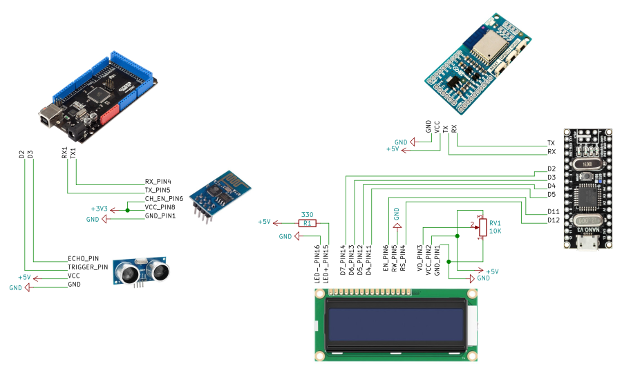
The schematic below shows how the peripherals for each client are connected. To supply voltage to the ultrasonic sensor and ESP-01 module a breadboard power supply module is used. The LCD and the Espresso Lite are connected to the 5v of the Arduino Nano. The Raspberry Pi is not shown on the schematic since it's independent of the two clients.
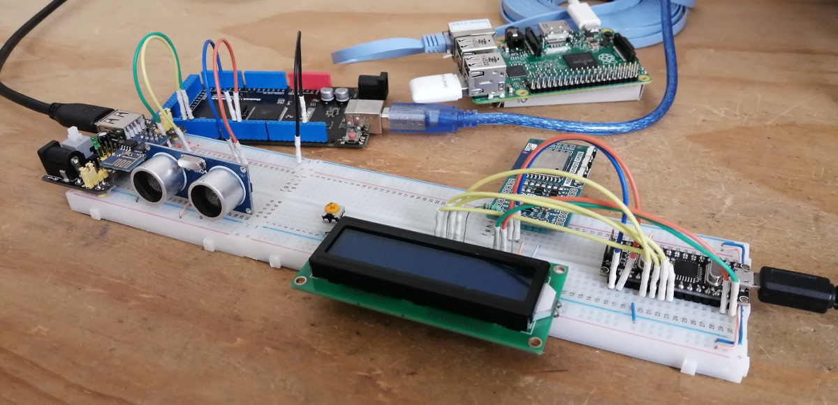
Here is a picture of how everything is connected on the breadboard.
Updating the firmware in both ESP modules
I bought the ESP-01 module and the Espresso Lite long time ago so the firmware intalled in them wasn't a recent one.
In the Espresso Lite I installed Espressif's firmware v1.7.4 and on the ESP-01 I installed the v1.6.2. To install the firmware I used the tool esptool.py v3.1 which can be downloaded from this github repo. Before flashing, download the two firmware versions from the Espressif's website.
To flash the firmware in the Espresso Lite run the following:
cd ESP8266_NonOS_AT_Bin_V1.7.4/ESP8266_NonOS_AT_Bin_V1.7.4/bin/at/1024+1024
./esptool.py --port /dev/ttyUSB0 write_flash --flash_freq 40m --flash_mode dio --flash_size 4MB 0x00000 ../../boot_v1.7.bin 0x01000 user1.2048.new.5.bin 0x1fc000 ../../esp_init_data_default_v08.bin 0xfe000 ../../blank.bin 0x1fe000 ../../blank.bin
For the ESP-01 execute the following:
cd ESP8266_AT_Bin_V1.6.2_0/ESP8266_AT_Bin_V1.6.2/bin/at/512+512/
./esptool.py --port /dev/ttyUSB1 write_flash --flash_freq 40m --flash_mode dio --flash_size 512KB 0x00000 ../../boot_v1.7.bin 0x01000 user1.1024.new.2.bin 0x7c000 ../../esp_init_data_default_v08.bin 0x7e000 ../../blank.bin
Issue with firmware v1.6.2
Unfortunately this version comes with errors which translate into the module disconnecting from the network after a minute or so. Although the solution will be to update the firmware to a recent version, the problem is that the external flash memory has only 512 KB because is and old version of this module.
Newer firmware versions require at least 1 MB of flash memory. Maybe later I'll buy a new version of this module or change it for another one like the ESP32-NodeMCU. For the moment it works for my basic setup but, needless to say, I will not use it for other projects.
Code for both clients
Both clients need the following libraries to send or read MQTT messages through WiFi.
- WiFiEsp - this library allows to the Arduino to communicate with the ESP module through AT commands.
- PubSubClient - this library allows the clients to connect to a broker and publish or subscribe to topics.
I used the Arduino IDE to program both Arduinos. I installed these libraries with the "Library Manager".
Code for the publisher
In general the code works as follows:
- First, setup the ESP-01 module so it connects to the WiFi network.
- Then connect to the MQTT broker to publish message in the topic "sensor/distance".
- Inside a loop calculate the distance to an object every 5 secs by triggering the ultrasonic sensor.
- Finally, publish the distance as a message into the topic.
#include "WiFiEsp.h"
#include "PubSubClient.h"

const int trig_pin = 2;
const int echo_pin = 3;

// WiFi credentials and variables
const char ssid[] = "SSID_NETWORK";
const char pswd[] = "PSWD_SSID";
int status = WL_IDLE_STATUS;

// MQTT variables
const char ip_broker[] = "192.168.1.252";
unsigned long last_send;

// Ultrasonic sensor variables
unsigned long duration;
unsigned int distance;

WiFiEspClient espClient;

PubSubClient client(espClient);

void setup() {
  // Init serial for debugging
  Serial.begin(115200);

  // Init serial for ESP module
  Serial1.begin(115200);

  // Init ESP module
  WiFi.init(&Serial1);

  // Check if module is connected
  if (WiFi.status() == WL_NO_SHIELD) {
    Serial.println("Wifi module is not connected");
    // Do not continue
    while (true);
  }

  // Attemp to connect to WiFi network
  while (status != WL_CONNECTED) {
    Serial.print("Attempting to connect to WPA SSID: ");
    Serial.println(ssid);

    // Connect to WPA/WPA2 network
    status = WiFi.begin(ssid, pswd);
  }

  // Attempt to connect to MQTT broker
  client.setServer(ip_broker, 1883);
  while (!client.connected()) {
    Serial.print("Attempting to connect to broker: ");
    Serial.println(ip_broker);

    if (client.connect("ESP8266Client")) {
      Serial.println("[DONE]");
    } else {
      Serial.print("[FAILED] [rc = ");
      Serial.print(client.state());
      Serial.println(" : retrying in 500ms]");
      delay(500);
    }
  }

  pinMode(trig_pin, OUTPUT);
  pinMode(echo_pin, INPUT);
}

void loop() {
  unsigned int distance;

  // Every 5 secs send a message with the distance
  // measured by the sensor
  if (millis() - last_send > 5000) {
    Serial.println("Send Topic");

    distance = get_distance();
    String payload = String("Distance: " + String(distance));

    char attributes[100];
    payload.toCharArray(attributes, 100);
    client.publish("sensor/distance", attributes);
    Serial.println(attributes);

    last_send = millis();
  }

  client.loop();
}

unsigned int get_distance(void)
{
  digitalWrite(trig_pin, LOW);
  delayMicroseconds(2);
  // Send pulse
  digitalWrite(trig_pin, HIGH);
  delayMicroseconds(10);
  digitalWrite(trig_pin, LOW);

  // Get echo and measure time travel
  duration = pulseIn(echo_pin, HIGH);
  distance = (duration * 0.034 / 2);

  return distance;
}
Code for the subscriber
For this client the code works as follows:
- Setup the Espresso Lite to connect it to the WiFi network.
- Connect it to the MQTT broker to read the messages in the topic "sensor/distance".
- Inside a loop wait for new messages from the topic and display them on the LCD.
#include
#include
#include

// WiFi credentials and variables
const char ssid[] = "SSID_NETWORK";
const char pswd[] = "PSWD_SSID";
int status = WL_IDLE_STATUS;

// MQTT variables
const char ip_broker[] = "192.168.1.252";

// LCD pinout
const int rs = 12, en = 11;
const int d4 = 5, d5 = 4, d6 = 3, d7 = 2;

LiquidCrystal lcd(rs, en, d4, d5, d6, d7);

WiFiClient espClient;

PubSubClient client(espClient);

void setup() {
  lcd.begin(16, 2);

  // Init serial for ESP module
  Serial.begin(115200);

  // Init ESP module
  WiFi.init(Serial);

  if (WiFi.status() == WL_NO_MODULE) {
    lcd.setCursor(0,0);
    lcd.print("No WiFi module");
    // Don't continue
    while(true);
  }

  WiFi.disconnect();
  WiFi.endAP();

  while (status != WL_CONNECTED) {
    status = WiFi.begin(ssid, pswd);
  }

  lcd.clear();
  lcd.print("WiFi connected");

  // Attempt to connect to MQTT broker
  client.setServer(ip_broker, 1883);
  client.setCallback(sub_callback);
  while (!client.connected()) {

    if (client.connect("ESP8266-Wroom2")) {
      client.subscribe("sensor/distance");
    } else {
      lcd.clear();
      lcd.setCursor(0,0);
      lcd.print("No broker");
      lcd.setCursor(0,1);
      lcd.print("Retrying...");
      delay(500);
    }
  }

  lcd.clear();
  lcd.print("Broker found");
}

void loop() {
  client.loop();
}

void sub_callback(char *topic, byte *payload, unsigned int msg_length) {
  lcd.clear();
  lcd.setCursor(0,0);

  for (uint8_t i = 0; i < msg_length; i++) {
    lcd.print((char)payload[i]);
  }

  #if defined ARDUINO_MEGA2560
  Serial.print("Message arrived [");
  Serial.print(topic);
  Serial.print("]: ");

  for (uint8_t i = 0; i < msg_length; i++) {
    Serial.print((char)payload[i]);
  }

  Serial.println();
  #endif
}
Publishing and reading messages
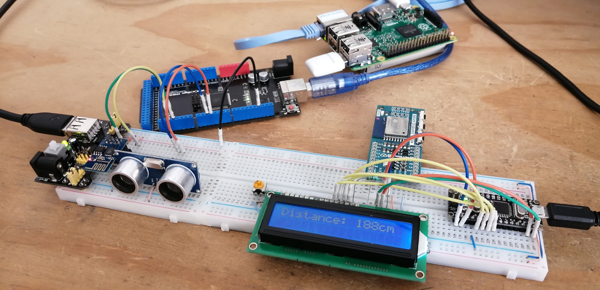
Here is a picture showing the LCD displaying the distance read from the topic. As I said before, due to the fault on the firmware in the ESP-01 the project works only for a few minutes.
If you buy a ESP-01S module it comes with a 1 MB of flash memory which is the minimum required for the v1.7.2 to work on it, so the code will run without any issue.


