Introduction
I started this project in 2021 with the goal of learning about Device Tree and Linux drivers. However, I lost interest, mainly because I found a job. I'm now getting back to it since new software is available for the Raspberry Pi, and I have other projects in mind based on this one.
When I started, the fbtft driver [1] was the only option for controlling these TFT displays. During my research, I found a new driver in development called tinydrm [2], which was not yet included in the Linux kernel. I ran some experiments, and I managed to successfully install the driver and get it working with the display. Time has passed, and the tinydrm driver is now part of the Linux kernel [3]. Therefore, the purpose of this tutorial is to describe the steps for installing these popular TFT displays on a Raspberry Pi using the tinydrm driver.
The following steps were performed using the hardware and software versions listed below:
- Hardware: Raspberry Pi 4
- Kernel Version: 6.12.47+rpt-rpi-v8
- Display: TFT ILI9341
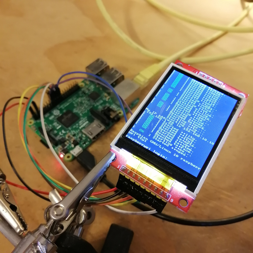
TFT display connections
The following table lists the wiring between the Raspberry Pi and the TFT display. Note that I am not using the backlight control pin in this setup, as I have connected it directly to 3.3V.
| TFT Display | Rpi GPIO | Rpi Pin |
|---|---|---|
| SCLK | GPIO 11 | 23 |
| MOSI | GPIO10 | 19 |
| CS | GPIO 8 | 24 |
| D/C | GPIO 24 | 18 |
| RESET | GPIO 25 | 22 |
| GND | ||
| VCC (3.3v) | ||
| BKL (3.3v) |
Setup for tinydrm driver
For this step, you need the Device Tree Compiler, which you can install using the following command:
sudo apt-get install -y device-tree-compiler
Write and compile devicetree overlay
To start, we need to write the following Device Tree Overlay to set up the pins for the driver.
// Enable ILITEK 9341 display
/dts-v1/;
/plugin/;

/ {
    compatible = "brcm,bcm2835";

    fragment@0 {
        target = <&spi0>;
        __overlay__ {
            /* needed to avoid dtc warning */
            #address-cells = <1>;
            #size-cells = <0>;
            status = "okay";

            ili9341: ili9341@0{
                compatible = "adafruit,yx240qv29";
                reg = <0>;
                pinctrl-names = "default";
                spi-max-frequency = <32000000>;
                rotation = <0>;
                reset-gpios = <&gpio 25 0>;
                dc-gpios = <&gpio 24 0>;
            };
        };
    };
};
According to the documentation, the display's backlight can be controlled via a Raspberry Pi GPIO [4] [5]. Although I haven't utilized that GPIO for my setup, I've left the necessary lines in the Device Tree Overlay if you wish to enable backlight control.
// Enable ILITEK 9341 display
/dts-v1/;
/plugin/;

/ {
    compatible = "brcm,bcm2835";

    fragment@0 {
        target-path="/";
        __overlay__ {
            backlight: ili9341-backlight{
                compatible = "gpio-backlight";
                gpios = <&gpio 18 0>;
                default-on;
            };
        };
    };

    fragment@1 {
        target = <&spi0>;
        __overlay__ {
            /* needed to avoid dtc warning */
            #address-cells = <1>;
            #size-cells = <0>;
            status = "okay";

            ili9341: ili9341@0{
                compatible = "adafruit,yx240qv29";
                reg = <0>;
                pinctrl-names = "default";
                spi-max-frequency = <32000000>;
                rotation = <0>;
                reset-gpios = <&gpio 25 0>;
                dc-gpios = <&gpio 24 0>;
                backlight = <&backlight>;
            };
        };
    };
};
Save this file in your home/ directory. With the overlay saved, we are now ready to compile it and apply the new pin configuration.
Compile and install devicetree overlay
Execute the following command to compile your Device Tree Overlay.
dtc -@ -Hepapr -I dts -O dtb -o ili9341-spi.dtbo ./ili9341-spi-overlay.dts
Move the .dtbo file to the /boot/firmware/overlays directory. Then, modify /boot/firmware/config.txt to enable the Device Tree Overlay, which will load the driver.
...

# Uncomment some or all of these to enable the optional hardware interfaces
#dtparam=i2c_arm=on
#dtparam=i2s=on
dtparam=spi=on
dtoverlay=spi0-cs

...

# Additional overlays and parameters are documented /boot/overlays/README
dtoverlay=ili9341-spi
After saving the changes, you must reboot the Raspberry Pi to load the driver.
Confirm driver is installed
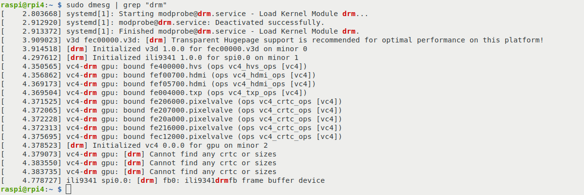
Check the kernel messages during the boot process to confirm that the driver has been successfully installed. To do this, execute the following command:
sudo dmesg | grep "drm"
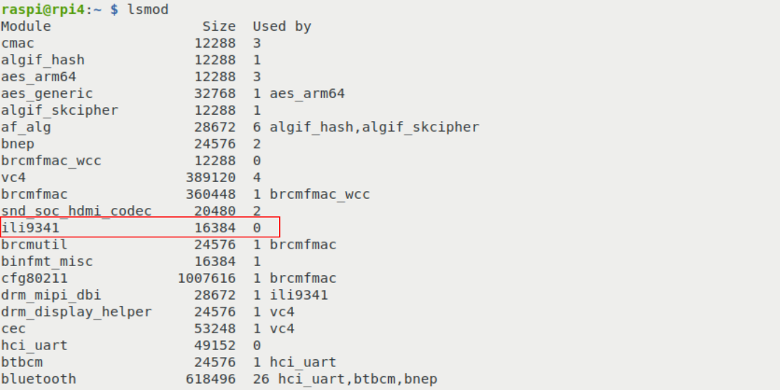
Run the following command to list all installed kernel modules. Specifically, check to see if the ili9341 kernel module is listed:
lsmod
Use the following command to check which graphics card number has been assigned to the display. In my setup, card1 was assigned to the TFT display:
ls -al /sys/class/drm/
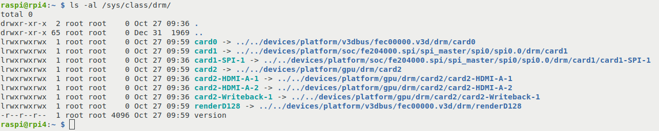
IMPORTANT: This assigned card number may change each time you boot the Raspberry Pi 4.
Verifying the Installation
The simplest test is to display the console on the screen. To achieve this, edit the /boot/firmware/cmdline.txt file and append the following command to the end of the line, redirecting the console to framebuffer 1 [6]:
fbcon=map:1 # or map:0, depending which frame buffer is set
Reboot the Raspberry Pi to apply the changes. Once the boot process initializes the driver, you should see the kernel messages on the display.
With the tinydrm driver now set up and verified, your display is ready for development. I hope this tutorial gives you a great starting point for all your future projects involving this hardware.